Bolted Joint Analysis using BOLTCALC Case study on a bolt loosening issue - Inch bolts used
Self-loosening of bolts and nuts is extremely common. In some situations it is an inconvenience, in others, disastrous consequences can arise. When bolts do come loose, it is due to specific causes, address those causes, and loosening will not occur.
This presentation presents a case study investigating the reason why bolt loosening was occurring on a drive sprocket on a tracked vehicle. This case study uses inch units and thread sizes. In many analyses the difficulty can be in establishing what are the forces acting on the joint and on individual regions of the joint associated with each bolt. This case study gives an overview of this process for the particular joint discussed.
Essentially, research indicates that self-loosening is the result of insufficient bolt preload to prevent joint movement when the forces applied to the joint and relaxation losses are taken into account. What this case study does is to investigate whether there is sufficient bolt preload to prevent joint movement. In general for the vast majority of joints, preventing joint movement from occurring will prevent self-loosening.
Forces acting on the joint
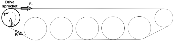
The forces acting on the drive sprocket are shown in the illustration. The forces are dynamic in that they will depend upon how the vehicle is driven and the conditions encountered.
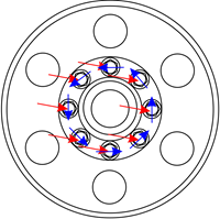
The forces acting on the joint can be reduced to a resultant force and a torque acting on the bolt group as shown in the image. The forces acting on each bolted region of the sprocket joint will vary depending upon its location. Since the sprocket rotates, the force acting on an individual region will fluctuate.
To complete the analysis, the maximum resultant force acting on any of the bolt regions is required to be established. By such means, it was established that the maximum resultant force acting on any individual bolted region was 2300 lbf.
The sprocket rotates the magnitude and direction of the resultant force would change. To prevent localised slip within an individual bolted region, the clamp force on the joint interface must create sufficient friction grip to resist this force. If localised slip was allowed to occur, fretting of the interfaces can occur causing a loss of preload and potentially bolt fatigue issues.
Joint details
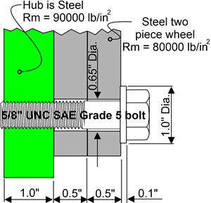
The sprocket joint comprises eight 5/8" UNC SAE grade 5 bolts. A cross section throught the joint is shown in the image.
A joint analysis will be performed using BOLTCALC to establish whether the joint is structurally sound, that is, whether a failure can be anticipated. The program will check whether the joint is adequate considering the following five possible failure modes: That there is sufficient bolt preload to resist the forces acting on the joint. That is, the joint plates will not slip nor separate. If the analysis indicates that the possibility of joint slip exists, then there is also the likelihood that the bolt can self-loosen. That the bolt will not sustain yielding as a result of the forces applied to the joint. In this case, there is only minimal axial force acting on the joint so this will not occur in the joint under study. That the bolt will not sustain fatigue failure. Since the axial loading is zero, fatigue failure would not be anticipated unless joint slip occurs. If it does, then the bolt can sustain bending due to the bolt head being dragged sidewards. That thread stripping will not occur. That the bearing pressure on each joint interface is within acceptable limits. Using BOLTCALC with this problem
The screen capture video below shows the program being used to investigate the loosening problem. The video is just over 20 minutes long. To get an enlarged view of the video, click on the enlarge control on the right hand side of the video control.
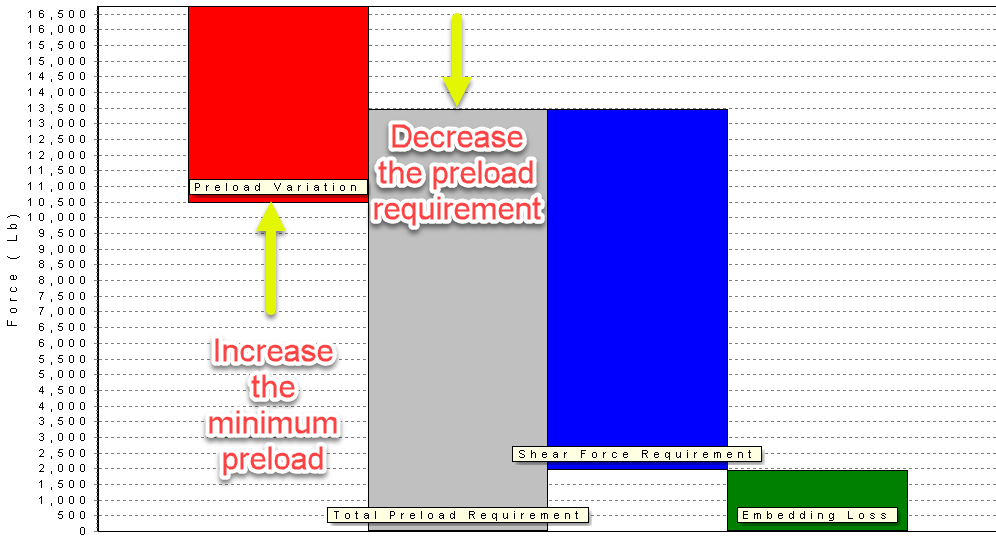
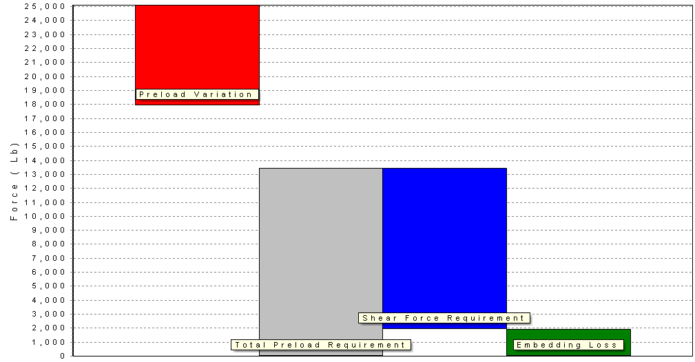
As indicated in the video, the analysis indicates that local joint slip is likely to occur. The preload requirement chart is shown below for the application. It may be decided that some form of locking device could be used to prevent the self-loosening from occurring, that is, prevent the rotation of the bolt. The issue can be is that if this loading was repeatedly applied, the bolt would be sustaining a bending stress as a result of the head being dragged sidewards. A loosening issue could then be replaced by a bolt fatigue issue maybe after a few months in service.
To resolve the issue completely, the minimum preload must be greater than the total preload requirement. So to resolve the problem you can increase the minimum preload (larger bolt, stronger bolt, better tightening process etc.) or, decrease the preload requirement (by reducing the shear force or increasing the interface friction). Reducing the shear force could be achieved by placing restrictions on the performance of the vehicle (which may be unacceptable to the end user) or increasing the number of bolts in the joint. Increasing the number of bolts would be an expensive option. Increasing the minimum preload could be achieved by increasing the bolt size, but again, this would be an expensive service fix. What will be investigated is whether by optimising the tightening torque and increasing the bolt strength, a solution could be obtained.
Revised analysis
A number of torque-tension tests were performed to check whether the tightening was optimal. This found that the minimum coefficient of friction was 0.1 as against 0.12 that was assumed. The video below shows the analysis modified to take account of the test results and the use of a property class 10.9 bolt. The video is just over 5 minutes long.
Hence, changing the design so that a SAE Grade 8 bolt is used with a tightening torque of 180 lb-ft should prevent joint slip from occurring, based upon the information entered into the program. Increasing the bolt strength could cause thread stripping to occur, in this case, BOLTCALC indicates that this will not occur. The final preload requirement chart is shown below. Whether a larger margin is required is a judgement call, it depends upon how reliable the data is that has been entered. Inn particular, how sure are you that the forces, and the coefficient of friction between the wheel and the hub, are correct. If doubt is present, a larger margin may be required. Perhaps assessing whether stronger bolts (such as property class 12.9) are appropriate for this application and whether the friction between the hub and the wheel should be experimentally determined.
Further InformationPresented below are links to further
information related to the BOLTCALC program: